



Abstract: Transformers are vital components in electrical power systems, used for voltage transformation, impedance matching, and electrical isolation. Due to their critical function, ensuring the reliability, safety, and performance of transformers is paramount. This is ensured by testing of power transformers which is governed by IEC 60076 or IEEE C57 standards. This document provides a brief explanation of all tests conducted on power transformers according to IEC 60076-1 and elaborates the purpose and significance of the same.
Introduction
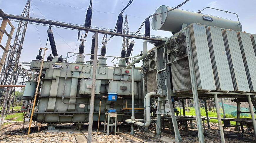
Power transformers are essential components in electrical power systems for stepping up or stepping down voltage levels, enabling efficient power transmission and distribution (Refer figure 1). Testing of power transformers is critically important for ensuring the reliable, efficient, and safe operation of electrical power systems. Below are the key reasons why power transformer testing is essential.
1. Ensures Operational Reliability
- Early Detection of Defects: Testing helps identify insulation breakdowns, winding faults, core issues, and tap changer malfunctions before they lead to catastrophic failures.
- Minimizes Downtime: Detecting problems early allows for planned maintenance, reducing the risk of unexpected outages.
2. Prevents Failures and Accidents
- Transformers are prone to faults due to overload, short circuits, or insulation failure.
- Testing helps prevent fire hazards, oil explosions, and electrical accidents caused by undetected faults.
3. Reduces Maintenance Costs
- Timely testing allows condition-based maintenance instead of routine replacement.
- Extends the lifespan of the transformer, optimizing the return on investment.
4. Validates Manufacturer Specifications
- Factory Acceptance Tests (FAT) and Site Acceptance Tests (SAT) verify that the transformer meets the specified performance and safety standards before commissioning.
5. Ensures Compliance with Standards
- Testing is necessary to comply with international standards (e.g., IEC, IEEE etc.
- It is often legally required for insurance, safety audits, and regulatory approvals.
6. Supports Grid Stability
- Transformers play a key role in voltage regulation and power distribution.
- Faulty transformers can lead to voltage drops, blackouts, or grid instability.
2.0 Important Transformer Tests
Transformer testing, as governed by the International Electro technical Commission (IEC) standards, specifically the IEC 60076 series, provides standardized guidelines for verifying the design, construction, and performance of power transformers.
2.1 Classification of Transformer Tests
According to IEC 60076-1, transformer tests are broadly classified into:
A. Routine Tests: These are performed on every transformer before dispatch from the factory to ensure basic operational compliance.
B. Type Tests: These tests validate the design and are typically carried out on one unit of a design type.
C. Special Tests: Performed at the customer’s request to obtain additional information or when the transformer operates under special conditions.
2.2 Routine Tests (IEC 60076-1)
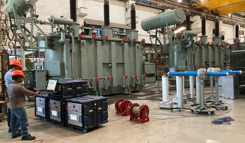
Different types of routine tests are described below (Refer figure 2):
1. Measurement of Winding Resistance: Performed on all windings to ensure proper winding connections and detect any potential defects like loose connections or broken strands.
- Equipment: DC resistance test set
- Acceptance: Deviation from calculated values must be within acceptable tolerances.
2. Measurement of Voltage Ratio and Check of Phase Displacement: Confirms that the transformer provides the correct voltage transformation and phase relationship.
- Done across all tap positions.
3. Measurement of Short-Circuit Impedance and Load Loss: Determines impedance voltage and load losses at rated current.
- Load losses must be within manufacturer’s declared values.
4. Measurement of No-Load Loss and Current: Establishes the core loss and excitation current at rated voltage.
- Performed at rated frequency.
5. Dielectric Tests: It Includes:
- Power Frequency Withstand Test (Applied Voltage Test)
- Induced Overvoltage Test
These tests ensure the insulation system can withstand specified voltages without breakdown.
6. Insulation Resistance Measurement: Checks the insulation resistance between windings and earth or between windings.
- Measured using insulation tester.
- Typical acceptable insulation resistance: >1000 MΩ for MV/HV systems.
2.3 Type Tests (IEC 60076-1, 60076-2, 60076-3)
1. Temperature Rise Test (IEC 60076-2): Evaluates the transformer’s thermal performance under rated load conditions.
- Carried out using the direct loading or simulated loading method.
- Determines hot-spot and top-oil temperature rise.
2. Lightning Impulse Test (IEC 60076-3): Ensures the transformer can withstand high voltage surges like those from lightning.
- Full wave and chopped wave impulses are applied.
- Voltage levels depend on transformer’s insulation class.
3. Switching Impulse Test (for transformers >72.5 kV): Simulates the effects of system switching operations.
4. Sound Level Measurement (IEC 60076-10): Assesses acoustic emissions, particularly for transformers in urban or noise-sensitive areas.
- Compliance is essential for noise regulation.
2.4 Special Tests (IEC 60076-1 and others)
Special tests are generally carried out based on the agreement between manufacturer and customer. Common ones include:
1. Dielectric Dissipation Factor (Tan Delta): Measures insulation health by evaluating dielectric losses.
- Acceptable Tan Delta for new transformers is typically < 0.5% at 20°C.
2. Partial Discharge Test: Detects localized insulation breakdown before full dielectric failure.
3. Short-Circuit Withstand Test (IEC 60076-5): Proves the mechanical strength of windings under high short-circuit currents.
- Not mandatory for every unit, often a type test. Requires sophisticated testing labs or verified simulations
4. Frequency Response Analysis (IEC 60076-18): Detects core movement or mechanical deformation, often used post-transportation or after fault events.
3.0 Stages of Transformer Testing
Transformers are tested at various stages like during manufacturing, factory acceptance testing (FAT), installation and commissioning, routine maintenance , diagnostic (condition monitoring) testing for defects or after failure, and post-mortem tests during scrapping (if possible). The purpose of testing at various stages are as follows:
1) Manufacturing stage – Testing at this stage aims to ensure windings are correctly connected and to detect defects or faults well before processing and oil-filling the transformer.
2) Factory Acceptance Testing -After processing, the fully assembled transformer is subjected to routine and type tests per customer specifications and relevant National standards to show that transformer performance and insulation meet the technical particulars required by the user and guaranteed by the manufacturer.
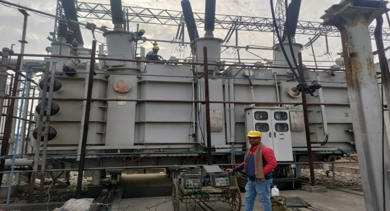
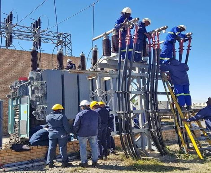
3) Installation & Commissioning stage- Transformers, specifically large units, are transported to the site after oil draining and filled with dry air. These are subjected to some simple tests soon after receipt at the site and after assembling all accessories but before oil filling. This ensures no transit damages and all electrical connections are correctly done. (Refer figure 3)
After filling the oil and filtration processtests are done to ensure that the transformer meets all aspects for energisation and to get signature parameters that can be used during maintenance to determine the transformer’s health condition.
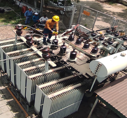
4) Maintenance tests- Thesetests are done at the time of periodic maintenance after taking shutdown. Some tests (DGA -Dissolved Gas Analysis, inspection by infrared thermometer, PD -Partial Discharge, and Vibration analysis) are done in live energised conditions. (Refer figure 4)
5) Tests after fault/failure- Tests are done to diagnose the fault’s cause, determine the location or part of the failure, and assess the extent of damage.
4.0 Tolerances and Acceptance Criteria
IEC 60076 allows specific tolerances to account for manufacturing variations. Exceeding these tolerances may result in rejection or rework of the transformer.
Table 1 – Tolerances as Per IEC 60076-1
| Item | Tolerance |
| 1. a) Total losses See Note 1 b) Measured component losses See Note 1 | +10 % of the total losses +15 % of each component loss, provided that the tolerance for total losses is not exceeded |
| 2. Measured voltage ratio at no load on principal tapping for a specified first pair of windings or the extreme tappings, if specified Measured voltage ratio on other tappings, same pair Measured voltage ratio for further pairs | The lower of the following values: ±0,5 % of the specified ratio±1/10 of the actual percentage impedance on the principal tapping ±0,5 % of the design value of turns ratio ±0,5 % of the design value of turns ratio |
| Measured short-circuit impedance for:a separate-winding transformer with two windings, ora specified first pair of separate windings in a multi-winding transformerprincipal tapping any other tapping of the pair | When the impedance value is ³10 % ±7,5 % of the specified value When the impedance value is <10 % ±10 % of the specified value When the impedance value is ³10 % ±10 % of the specified value When the impedance value is <10 % ±15 % of the specified value |
| Measured short-circuit impedance for:an auto-connected pair of winding, ora specified second pair of separate windings in a multi-winding transformerprincipal tappingany other tapping of the pair – further pairs of windings | ±10 % of the specified value ±10 % of the design value for that tapping To be agreed, but ³±15 % |
| 5. Measured no-load current | +30 % of the design value |
| NOTE 1– The loss tolerances of multi-winding transformers apply to every pair of windings unless the guarantee states that they apply to a given load condition. NOTE 2– For certain auto-transformers and series transformers the low value of their impedance may justify a more liberal tolerance. Transformers having large tapping ranges, particularly if the range is asymmetrical, may also require special consideration. On the other hand, for example, when a transformer is to be combined with previously existing units, it may be justified to specify and agree on narrower impedance tolerances. Any special tolerances should be indicated in the enquiry, and any revised tolerances agreed upon between manufacturer and purchaser. | |
5.0. Safety Considerations & Best Practices in Testing
5.1 Transformer testing involves high voltages and currents; hence, safety precautions must include:
- Use of personal protective equipment (PPE) (Refer figure 5)
- Adequate earthing
- Isolation of test area
- Emergency stop mechanisms
- Use of warning signage
5.2 Best Practices in Routine Testing
- Calibrate all test instruments before use.
- Perform tests in a clean, dry, and safe environment.
- Document all test results with timestamps and operator names.
- Review trends in test data over production batches to detect systemic issues.
6.0 Conclusion
Power transformers are essential components in electrical power systems for stepping up or stepping down voltage levels, enabling efficient power transmission and distribution. Given their critical role, thorough testing is mandatory to ensure safety, reliability, and compliance with design specifications. Transformer testing as outlined in IEC 60076 is a cornerstone of quality assurance in power system infrastructure. By systematically conducting routine, type, and special tests, manufacturers and utilities ensure that transformers meet the desired technical and safety standards. As grid demands grow and transformer applications become more complex, adherence to these globally accepted testing standards remains vital for long-term reliability and system resilience.
Last but not the least Condition monitoring through various test of power transformers is essential for maintaining the health, performance, and reliability of electrical power systems. Rather than waiting for a failure to occur, condition monitoring focuses on real-time or periodic assessment to detect early signs of deterioration or faults. Implementing a robust monitoring strategy can significantly reduce operational risks, enhance system reliability, and optimize maintenance costs.
By – Dr. Rajesh Kumar Arora
